Doubly Connected Edge List: Building
Introduction
A polygonal mesh is a collection of vertices, edges, and faces that together define the shape of a 3D object. There are many ways to represent a mesh in data structures, but one of the most widely used is the Doubly Connected Edge List (DCEL) - more commonly known as the Halfedge structure. Despite how often it’s mentioned in computer graphics, there isn’t that much clear, step-by-step information online about how to actually build it or work with it. That’s what motivated me to write this guide.
Before we dive in, a quick disclaimer: this article is not a full-fledged reference. A production-ready implementation of Halfedge has to deal with many tricky corner cases, and I’ll be skipping most of them here for the sake of clarity. The goal is to understand the core idea and the logic behind the structure.
To get started, all we need is a list of faces with a consistent orientation - for simplicity, we’ll assume all faces are oriented counterclockwise. In the Halfedge model, every edge is split into two directed halfedges pointing in opposite directions. This simple definition immediately highlights an important issue: in real meshes, edges don’t always have exactly two incident faces. If they have only one, we call them boundary edges. If they have more than two, they’re non-manifold edges, and handling those correctly is a lot more complicated. For this article, we’ll assume the mesh is “well-behaved” and avoid the non-manifold case.
At the core of the structure is the halfedge itself. Each halfedge stores three key pieces of information:
- the vertex it originates from,
- the face to its left,
- the next halfedge along that face.
Optionally, a halfedge may also store:
- the edge it belongs to,
- its twin (the opposite halfedge that lies on the neighboring face).
In some implementations, these optional values can even be derived implicitly through simple index arithmetic. Others also include a pointer to the previous halfedge, though this isn’t strictly necessary, since it can be found by walking the face in order.
Finally, Halfedge structures can be implemented either with pointers or with indices. In practice, index-based implementations tend to be more compact, easier to serialize, and often just more convenient to work with. That’s the approach I’ll be using in the rest of this article.
Internal structure
Let’s get started. Below are all the core structures we’ll be working with:
| |
Their purpose has already been covered in the introduction, so there’s no need to repeat it here. The code is fairly self-explanatory, and in this case it speaks louder than words.
Building
Before we start building the structure, we need to allocate space for the vertex and face arrays. This is necessary because we’ll be accessing them by index during construction. Why do we calculate the vertex array size this way? Typically, mesh vertices are numbered starting from zero, which means the maximum vertex index across all faces will always be one less than the total vertex count. That’s why we add +1 when computing the size.
| |
The next step is to collect information about the edges. For each face, the last edge loops back to the first one. As a result, the index of that edge in the edge array differs from the current edge index by the size of the face. We go through the vertices of each face in order and record: the source and target vertices of the edge, the index of the next halfedge, and the face index.
| |
Once we have the EdgeData, filling most of the half-edge fields is straightforward: the source vertex, the face to the left, and the pointer to the next half-edge. Each face, in turn, always points to the first half-edge belonging to it. At this point, the only remaining fields to fill are the edge and the twin halfedge.
| |
The final step is to establish connections between halfedges by filling in the edge and twin information. The logic here is simple: when we encounter an edge for the first time, we record it. When we see the same edge again but with reversed vertex order, we’ve found its twin and can link the two halfedges together. Keep in mind that this code assumes the mesh is well-formed, where each edge has at most two adjacent faces. For non-manifold geometry (for example, when more than two faces share the same edge), different handling would be required.
| |
Testing
For a simple test, let’s use a cube:
| |
Below is a diagram for clarity:
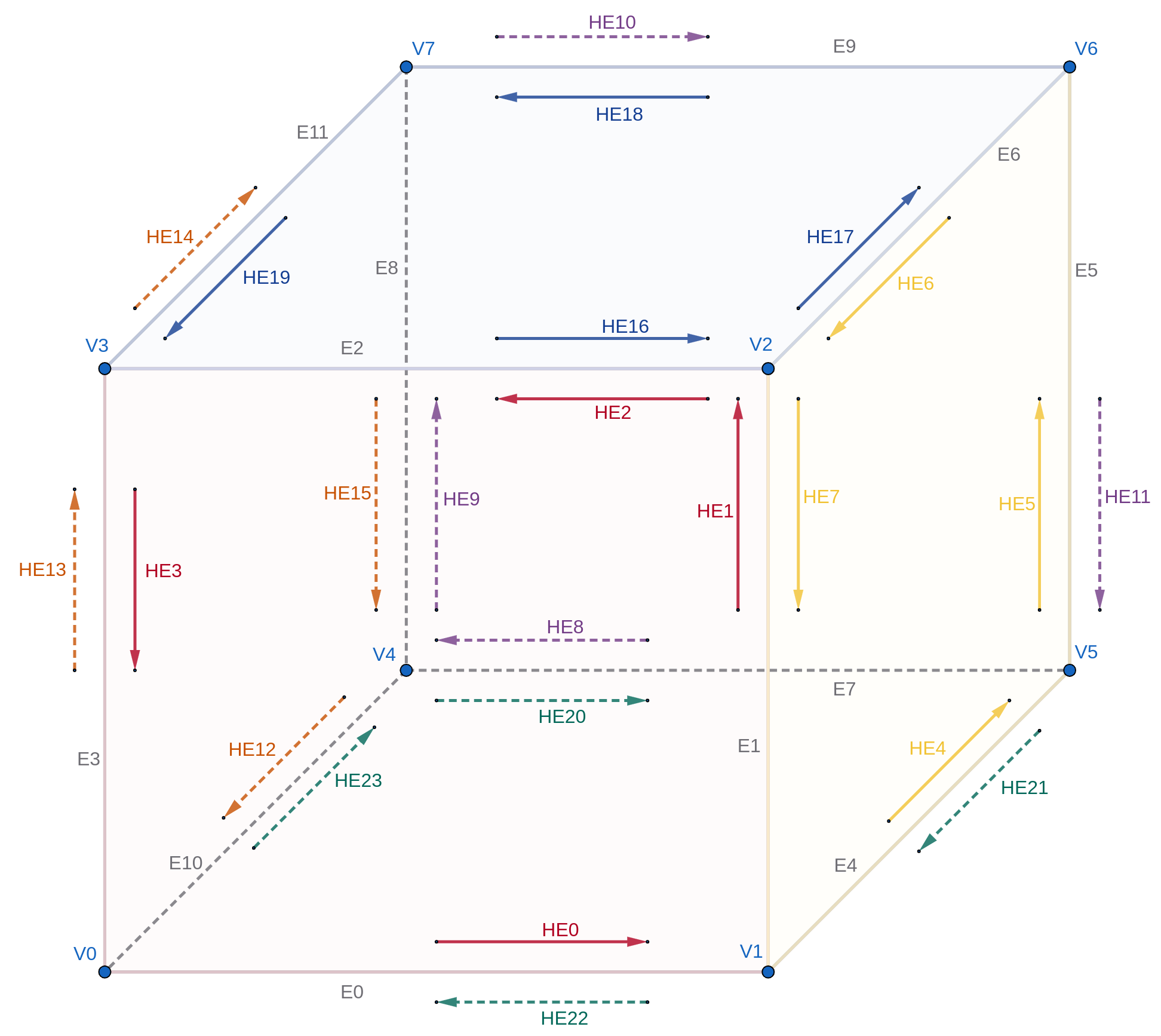
The full tests can be found in the complete program provided in the conclusion. They are fairly straightforward and mainly serve to verify that the structure is built correctly.
Conclusion
Here is the complete code for building the Halfedge structure. As we can see, for meshes where every edge connects exactly two faces, the implementation is fairly straightforward. I hope to cover more complex cases in future articles in this series.
In the next article, I plan to dive into navigating the resulting structure. For well-defined, boundary-free meshes, this task is not particularly difficult.
Show sources
| |
Sources
- Half-Edge Data Structures by Jerry Yin and Jeffrey Goh
- Halfedge mesh internals in Geometry Central documentation
- Half-edge based mesh representations: theory
- Half-edge based mesh representations: practice
- Half-edge data structure considered harmful
- The Polygon Mesh Processing Library github
- Geometry Central github
- Yotam Gingold halfedge implementation github